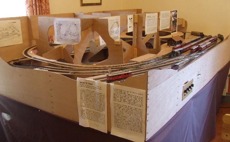
indentSome of you may know that I took
this layout, just as you see here, to the Wells model railway exhibition a few years back.
To offer some continuous movement, (there being no scenery one has to have
something to attract the punters and movement's as good as anything), I temporarily linked
tunnel mouths lower "C" and "B" which made a loop. The track
layout was not quite as drawn here (it was version 4g at the time). I had not added
the link between the middle AC goods road and the island platform line, nor the extra
point to divide the AC sidings into three: I had not thought of it then! (It was
only after the exhibition that I realised the need for more space to
"put" things in which had arrived, without having to interrupt movements on the
main DC lines.) But I had a terminus (the AC part of the station), a continuous run,
a passing station (the DC side), and a line "off-stage" to a return loop which
held 3 trains: I was in business! While a train circulated on the loop I was able to
either shunt at the front or move a railcar from the short bay at this end down to the
return loop or I could "operate", swapping one circulating train for another,
running round it at one end or sending it down to the storage loop to change it for
another. Actually, it was great fun! It did prove however that Bemo couplings
need a bit of work and that once the catenary is in place, automatic un-couplers will be a
"must". |
|
|
indentIf you have
studied the track plan (No? 'ere ya then...)
you will see that we had got no further than the first layer. Now, very many months
later, there is little more construction to show for the break but a) the workshop's very
cold in winter, b) I've had other things to do, not least a spell in Shropshire working
for another customer but mainly because c) I needed to have a re-think after the
experience of Wells and change the plans a bit.
indentThis was mainly to do with the wiring. When I
first loaded the layout up with stock early Saturday (after having worked right through
the previous Thursday night to get the lowest DC return loops working, getting there early
Friday evening and then carry it all in and setting up), I found I kept getting
unaccountable short circuits which would, frustratingly, bring everything to a grinding
halt! This turned out to be the fact that the more modern EwIII coaches have wiring
which links all the wheels on one side of the coach. I am using Peco points which
change the polarity of the un-selected road instead of actually isolating it.
Therefore, if you park a train of EwIII-coaches on any loop siding you have a mobile short
circuit! Knowing this would be a problem with locos with long wheelbases and
"all-wheel pickup", I had moved the isolating gaps to the middle of the loops to
keep clear of them; ending up with them bang in the middle of the coaches - hence the
short circuits! For the exhibition that was easily got round by ensuring I stopped
the trains with only couplings bridging the insulation gaps but I would have to change the
whole wiring approach for the permanent layout! |
|
|
Setting out full size.
indentThe experience of operating at Wells also suggested
more could be got from the track layout by moving a few points a little bit this way and a
few others a little bit that. Therefore a complete relay is now in prospect- but I would
have had to lift the track anyway because I want to lay it on a foam trackbed to improve
track-dirt resistance and reduce noise; both products of vibration.
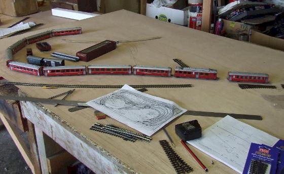
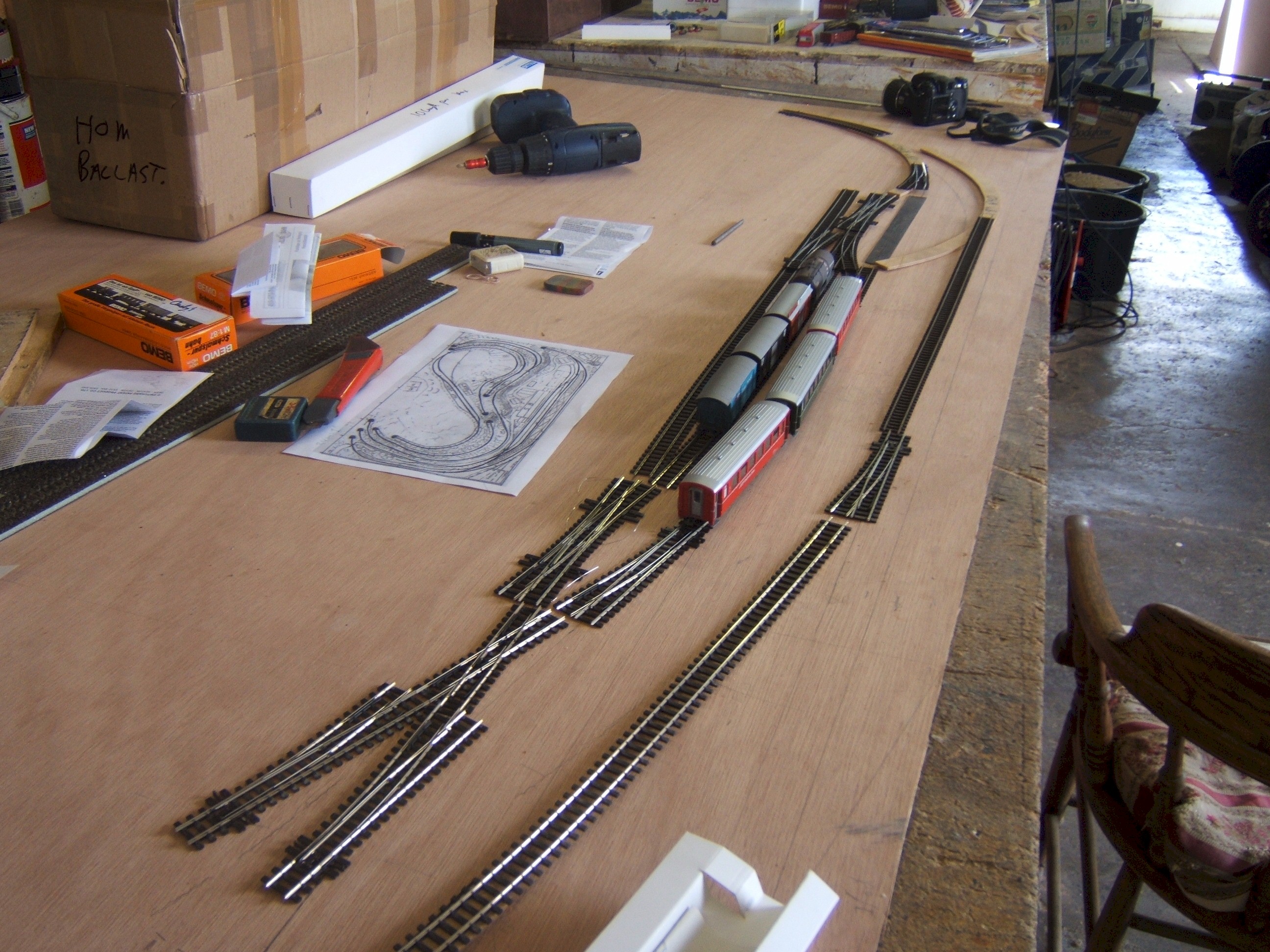
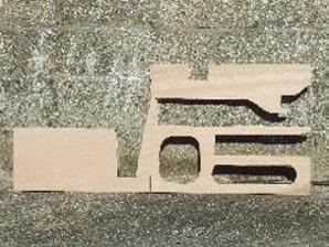
indentOf course, before I could get as far as exhibiting even
a naescent layout, the plan had to be drawn out full-size on the 4mm plywood trackbed; a
job best done using real points and the proper rolling stock. (t See left.) At that stage I confirmed what I had
previously expected; it would not be possible in such a tight space to fit in the train
lengths and shunting necks I wanted without "doctoring" some of the points and
perhaps even making a few by hand. Even after taking some time to get this right,
one still has to turn a 2-dimensional ply sheet into a 3-dimensional model. With
gradients almost as steep as the original's 1:14 (mine are 1:15; they need to be, Bemo
locos do not quite have
|
|
the weight of the real thing, as I found out when I tested
them! See test rig photo. A
four-coach train was fine but the 50s can handle 5 coaches which the Bemo model could not,
quite. So I lessened the gradient to 1 in 15 and all was well!
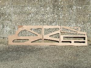
indentAt these kind of gradients one cannot work just from
plywood cut to a flat plan as it changes shape dramatically when you lift it to the
required slope. Therefore you start by marking everything out
full-size on a flat sheet - or in this case two - and then making the supports with the
curves and straights in the right places. So that comes next... |
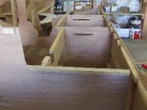
indentHow do you hold this lot
up? Well, I used what I call the "rib and spine" method. (See right.
u) First of all the track plan has to be confirmed.
Then the location of point motors and uncoupler sole- noids chosen and marked out.
Then you can decide where to put the timbers (ribs) for supporting the station area.
These verticals are more 4mm ply, glued together with 15mm square timber braces. I
have these square sections especially cut to size for me in a very light "red"
wood at the local saw mill. |
|
|
|
|
indentThe completed support structures
are going to be one complete piece in plan but two boards high; each
8 feet by 2 feet high by 4 ft 9 inches wide at the bottom and just under 4 feet wide
above. Not easy to carry so they need to be as light as possible, hence the thin ply
and lightweight wood. Finally this skeleton is fitted to shaped fascia pieces and
the individual pieces of "track bed" are cut to shape and fitted. On
laying a gradient, one piece starts it and then each curved part is cut from a different
sheet making sure each section overlaps. Then you can fit each one to the support
structure knowing it will be in the right place and simply trim the joints to the right
length as you assemble them. Easy once you've worked it out! |
|
indentSo, with the lower timberwork
all but completed - and I now have various bridges and viaducts as commercial foam
structures, again to save weight - I hope to arrange the supports to hold them in the
right places and move on. Having wired up and tested the lower DC loops the next job
is to make and fit the control panel, relay and wire up the main station and, after
fitting some catenary, to fit and wire the AC sidings too. All that, of course,
cannot be done until the control panel has been built. To do that I needed a wiring
diagram and to complete that I needed to know the signalling arrangements, now more or
less - if not entirely - understood. So, with most of the graphic diagrams
completed bar signalling, and the necessary components to hand, all I am waiting for
now is this raw Easterly wind to die away and spring to finally arrive so I can make some
more substantive progress. When I do, you will be the first to know!
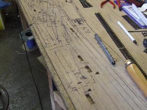
As we get towards the end of 2013,
progress has been both stilted and often come to a halt altogether. This, sadly, is
because Ken, who ordered and inspired this model, passed away a couple of years ago
leaving the project in limbo. Before he did so, the main track and pointwork of
'Pontravina' was completely re-laid, fitting the electrical insulating gaps needed for
correct operation adding tinned copper wire 'dropper's, trimming the over-long Peco
sleepers and ballasting as I went. You can see the results in the following images: |