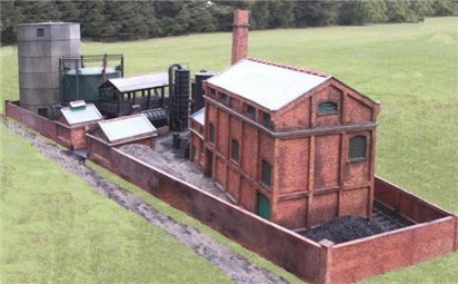
Our most recent commission has been to build a model gas works.

Here's a ¾ view from the Retort House end...

 Click here to move 
 to a plan and key 
 to what's what.

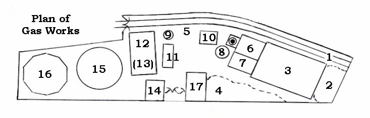
The details of which bit does what are contained in the plan and key below.

 Click here to move 
 to a description.
1  Coal arrival siding  Coal is shovelled into 2 or 3. 10  Tar Tank   Collects tar from 3, 8 and 9 for resale.
2  Coal Stack.  Enough kept for 24 hour's use. 11 Washer  Washes impurities from the gas.
3  Retort House  Here the coal is loaded into the retorts. 12  (top bit) Purifier Boxes   Removes "eggy" smell.
4  Coke Heap.  Coke is the biggest by-product. 13  (lower bit) used & clean Iron Oxide bins for purifiers.
5  Coke Loading Area  For coke unsold locally. 14  Meter House   Meters the amount of gas produced.
6  The Boiler House with its chimney. 15 Column-Guided Gas Holder   The familiar type!
7  The Exhauster House  Powered by the boiler. 16  MAN Water-less Gas Holder   A 20s innovation.
8  Condenser  Cools the gas. 17  Site & Sales offices   (Coke was sold by the bag
9  Tower Scrubber   Removes particulate impurities. at many a smaller gas works, often removed by old pram!)
 Click here to move 
 to next photo.

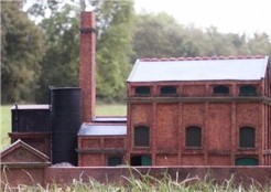
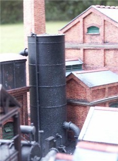
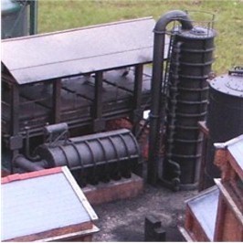
indentAnother view showing the Retort House where the gas is made. To its left are, at the front the Exhauster House (which pumps the gas around the site) and behind it the Boiler House (with chimney) which powers the pump. 

indentTo the left of those a tall black cylinder is the Condenser which cools the hot gas and to the left of that, the Tar Tank.  This collects the tar given off by the retort house, condenser and Tower Scrubber and stores it for resale.

indentThe condenser itself is a piece of equipment which helps date the model.  So far modellers have reproduced either early air-cooled serpentine condensers or the Victorian tubular "Annular Condensers" but these were replaced from the 1930s onwards by more efficient condensers in which electricity was used to pump water through the gas in tubes (like a loco boiler in reverse). 

indentThe large pipes feed the gas through the equipment, the small one running up the side feeds the water in while the small bent one at the bottom is the electricity supply running from the equipment cabinet next to it.

 Click here to move 
 to next photo.
 Click here to move 
 to next photo.

indentIt is worth noting that this model represents a gas works situated in the South of England because it was 
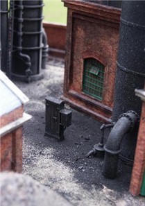
commissioned for a SR ex-LB&SCR layout set around World War 2. 
indentIn Sussex brick was the normal building material so our gasworks had to follow suit.  You can see therefore that not only do we attempt to choose appropriate equipment for the period modelled but that we also try to use the correct materials for the geographical setting.

indentThis photo also shows the route the coke unsold locally (i.e. most of it!) would have been barrowed over to reach railway wagons - another very useful source of model railway traffic.

indentThe next piece of equipment in our gas trail is the Tower Scrubber (the tall round sectional thing on the right).  This removed the larger "particulates" suspended in the gas.

indentThe similar horizontal cylindrical tank on a brick and concrete plinth is the Washer.  This removed ammonia before the gas passed on to the elevated struture behind it.

 Click here to move 
 to next photo.

"I'm bored with all this; can I go back to the general stuff?"  Yes.

 Click here to move 
 to next photo.

indentHere we have the Purifier.  This consisted of 4 boxes containing Iron Oxide.   Passing the gas through these removed the Sulphur, which was what caused the "rotten egg" smell which was so familiar around gas works all those years ago when there were leaks. 

indentIn the foreground is the vent on the roof of the Meter House where the gas was metered before being pumped into the holders.

 Click here to move 
 to the next General 
 Gallery photo.

indentAnd, finally, both we and the gas come to the holders.  The tall one clad in corrugated sheet is a M.A.N. "dry" or "waterless" gas holder.  Normal gasholders sat in a tank of water which sealed the gas in. This type had a sealed tube with a piston which moved up and down, rather like a bicycle pump.

indentLurking behind it is the more familiar type, properly known as a "Column-guided Gas Holder".

indentSo there you have it! A fair-sized 4mm scale model gas works in about 3½ feet (450cm) by just over a foot at the widest point.  Yes, it is a bit cramped but then most model railways are far more cramped than they should be so nothing new there!  An interesting project and a very enjoyable model to make, probably because it was such a departure from the normal pretty cottages and railway structures with which we are so familiar.  We hope you have enjoyed seeing it too!

So this is how Way out of Gallery... Return to "Gallery General" entrance Move on to next Gallery General page. he does spaces!