 |
Our most recently completed
commission
has been a model gas works.
It looks like this...
|
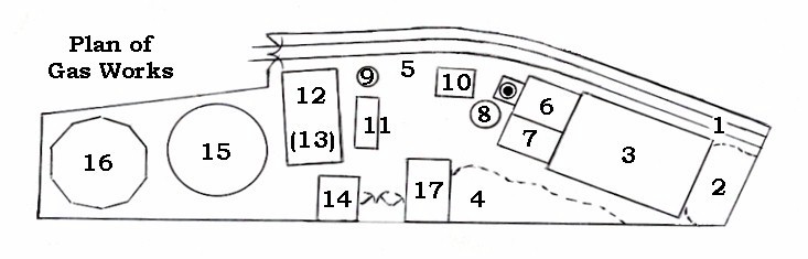
Here we see the model Gas Works from the "business
end".
The details of which bit does what are contained in the key below the plan.
model railways
 |
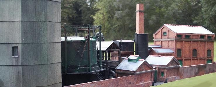
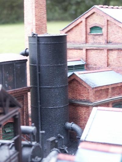
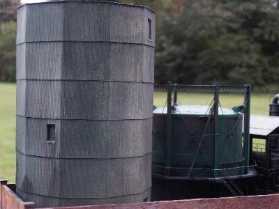
indentAnother view showing the Retort House. To its left are,
at the front, the Exhauster House and behind it the Boiler House with its enormous
chimney. To the left of those is a tall black cylinder which is the Electric
Condenser and to the left of that, the Tar Tank. |
model railways
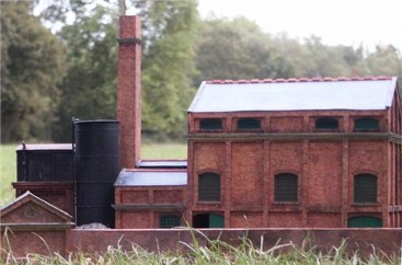
indentBefore we get to the condenser itself, note that the Retort House features vents at the top of all its walls, as well as more along the roof, to let any leaking gas out. The Boiler House too has a vent (it gets hot in there!), and around the edge of all the massively contructed brick buildings is a stone course of the type so beloved by the Victorians. Up until the Second World War many gas works were given architectural ornamentation to a greater (Victorian and Edwardian ones) or lesser (post WW1 buildings) extent until World War 2 when such fripperies seemed suddenly unimportant. This helps us date our model as an early Vertical Retort House from pre-WW2. indentNow we can move onto the condenser itself which is another piece of equipment which helps the knowledgeable date the model. So far modellers have reproduced either early 19th C. air-cooled condensers or the later Victorian water-cooled "Annular Condensers". From the 1930s onwards these were gradually replaced with more efficient types in which the water was pumped through tubes to cool the gas. The version we have chosen to model is is one of the tubular type, others were rectangular; often in multiples. |
 |
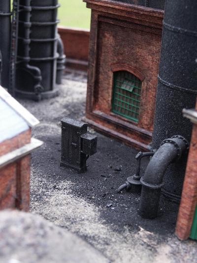
indentThe large pipes feed the gas through the equipment, the small one rising to the top feeds the water in while the small bent one at the bottom is the electricity supply provided from the equipment cabinet next to it. To the left of the condenser can be seen part of the Tar Tank which collects the tar produced by creating gas.
 |
indentThe Tar Tank is one of the simplest models since in a small works such as this, a normal model railway water tank is as good as anything! This kit one is mounted on brickwork to (almost) match the rest of the buildings. indentIt is worth noting that this model
represents a gas works situated in the South of England. This is because the layout
it was commissioned for is modelled on an ex-LB&SCR location and dated around World
War 2. |
indentBefore moving on; if you'd like to know what traffic a gas works could create on your railway, click here!
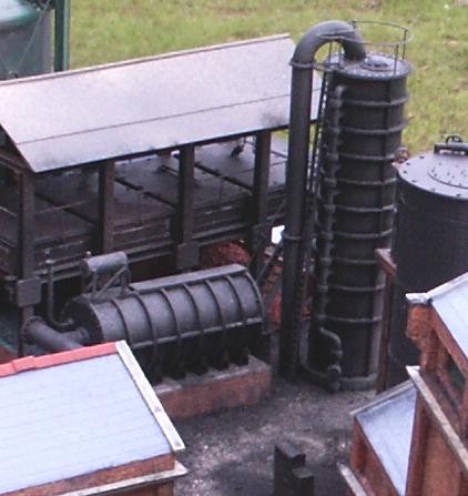
indentThe next piece of equipment in our gas
trail is the Tower Scrubber (the tall round sectional thing on the right). These
sections - the number varied according to the size of the works - were filled with coke
and sprayed with water; hence the numerous small pipes to each section. The unit
removed the larger "particulates" or bits of coke, tar and dust which were
suspended in the gas. indentThe similar horizontal cylindrical tank on a brick and concrete plinth is the Washer. This removed most of the ammonia before the gas passed on to the elevated struture behind it. |
 |
"I'm bored with all this; can I go back to the general stuff?" Yes.
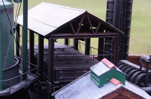 |
indentHere we have the Purifier. This consists of 4 boxes containing Iron Oxide. Passing the gas through these removed the sulphur which, when it leaked out, caused the "rotten egg" smell which was so familiar around gas works all those years ago. indentIn the foreground is the vent on the roof of the Meter House where the gas was metered before being pumped into the holders. |
model railways
indent And, finally,
both we and the gas come to those most familiar of gas works features, the holders.
In all but the smallest works there were at least two so that one could be kept in use
while the other was serviced or repaired. The tall one clad in corrugated sheet is a
M.A.N. "dry" or "waterless" gas holder. Normal gasholders sat in
a tank of water which sealed the gas in. This type had a sealed tube with a piston which
moved up and down, rather like a bicycle pump. |
 |
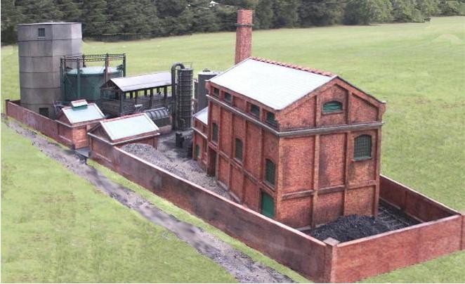
indentSo, with a final look at the whole model from the gas holder end; there you have it! A model gas works in about 3½ feet (450cm) by just over a foot at the widest point. Yes, it is a bit cramped but then most model railways are far more cramped than reality so nothing unusual there! An interesting project and a very enjoyable model to make, probably because it was such a departure from the normal railway structures and pretty cottages with which we are so familiar.
| So this is how | Way out of Gallery... | Return to "Gallery General" entrance | Move on to next Gallery General page. | he does spaces! |